Participating Media
← Back to Home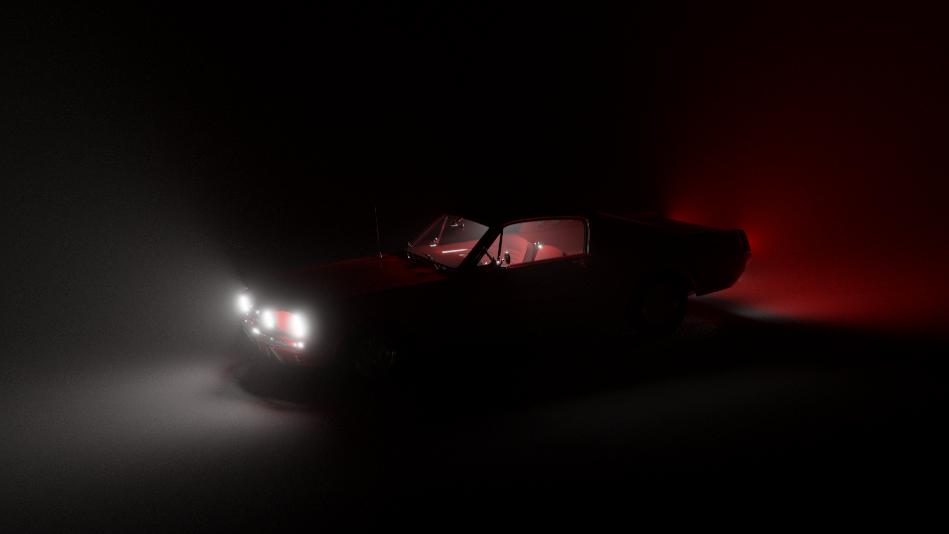
Participating Media
I implement two distinct types of volumes:
- Nested Volumes - Volumes contained within mesh boundaries
- AABB volumes - Volumes contained within axis aligned bounding boxes
Why Two Separate Approaches?
The main challenge was determining whether a point is inside or outside a volume. For mesh-based volumes, this requires ray casting to count boundary intersections (odd = inside, even = outside). But this approach has problems:
- Mesh requirements: Must be perfectly watertight with no holes or non-manifold geometry.
- Performance cost: This requires additional expensive ray queries per pixel for every volume in the scene, scaling poorly with scene complexity. Also, transmittance calculations for NEE require even more ray queries. This time on every bounce.
Axis Aligned Bounding Boxes
AABBs solve these problems. Ray AABB intersection tests are fast and simple. So for large scene spanning volumes, I use AABBs. Mesh volumes are still useful for subsurface scattering, but with performance limitations: rays spawning inside mesh volumes ignore scattering, and NEE is disabled within them.
Nested Volumes
For mesh volumes, I use a global flag in the ray payload to track inside/outside state. When a ray enters through refraction, the flag is set to true; when exiting, it's set to false. This eliminates the need for expensive intersection tests during traversal.
AABB Volumes
AABB volumes work similarly but perform intersection tests every time since rays can spawn inside them and transmittance for NEE has to be calculated. The math is dirt cheap, so even multiple volumes don't cause any performance issues.
Scattering Inside Volumes
To simulate scattering I use a simple tracking approach. I implemented it according to this article and Production Volume Rendering paper. Distance along the ray at which scattering has occurred is given by: $$ t = -\frac{\ln(1 - \xi)}{\sigma_t} $$
If this distance is shorter than the distance to the other side of the volume, or any other closest geometry, the ray has scattered inside the volume.
To get the scattering direction I used phase function $p(\mathbf{V} \cdot \mathbf{L})$. I decided to use Henyey-Greenstein since it's really easy to implement and use. $$ p(\mathbf{V} \cdot \mathbf{L}) = \frac{1}{4\pi} \cdot \frac{1 - g^2}{(1 + g^2 - 2g(\mathbf{V} \cdot \mathbf{L}))^{\frac{3}{2}}} $$ So to sample the direction I had to use inverse transform sampling: $$ \mathbf{V} \cdot \mathbf{L} = \begin{cases} \frac{1}{2g}(1 + g^2 - (\frac{1 - g^2}{1 - g + 2g \xi_1})^2) & if & g \neq 0\\ 1 - 2 \xi_1 & if & g = 0 \end{cases} $$ The problem was that this gives only the cosine of the angle between $\mathbf{V}$ and $\mathbf{L}$. To get the full 3D direction, another angle around the cone has to be sampled and a 3D direction has to be created from both of them. $$ \begin{gather*} \sin\theta = \sqrt{1 - (\mathbf{V} \cdot \mathbf{L})^2}\\ \phi = 2\pi \xi_2 \end{gather*} $$ So first I constructed $\mathbf{L}$ in a coordinate system where $\mathbf{V}$ points along the z-axis, and then transformed it to world space using orthonormal basis around $\mathbf{V}$: $$ \begin{gather*} \mathbf{L}_{local} = (\sin\theta \cos\phi, \sin\theta \sin\phi, \mathbf{V} \cdot \mathbf{L})\\\\ \mathbf{T}_1 = \begin{cases} \text{normalize}(\mathbf{V} \times (0, 0, 1)) & \text{if } |\mathbf{V}_y| = 1\\ \text{normalize}(\mathbf{V} \times (0, 1, 0)) & \text{otherwise} \end{cases}\\\\ \mathbf{T}_2 = \mathbf{V} \times \mathbf{T}_1\\\\ \mathbf{L} = \mathbf{L}_{local}.x \cdot \mathbf{T}_1 + \mathbf{L}_{local}.y \cdot \mathbf{T}_2 + \mathbf{L}_{local}.z \cdot \mathbf{V} \end{gather*} $$ The rest was easy. Since both $\mathbf{V}$ and $\mathbf{L}$ were in place, all that's left was to evaluate how much light gets scattered from $\mathbf{L}$ to $\mathbf{V}$. BxDF $f = \mathbf{C} \cdot p$. $\mathbf{C}$ being the medium color. And PDF is just the phase function $p$. With this, it's possible to simulate a lot of effects, subsurface scattering being the best example.
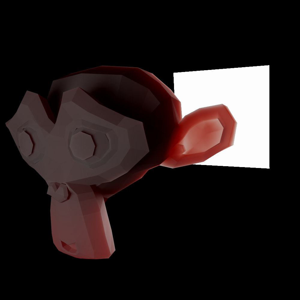
Subsurface Suzanne
This gives materials a more waxy look because light can penetrate the surface and exit on the same side but in a different location, as opposed to reflecting immediately. It's a pretty expensive simulation since the medium has to be really dense, and a lot of scattering events have to be simulated. So usually for rendering, subsurface scattering is just approximated using different and more efficient methods. But with this, it's almost as accurate as you can get.
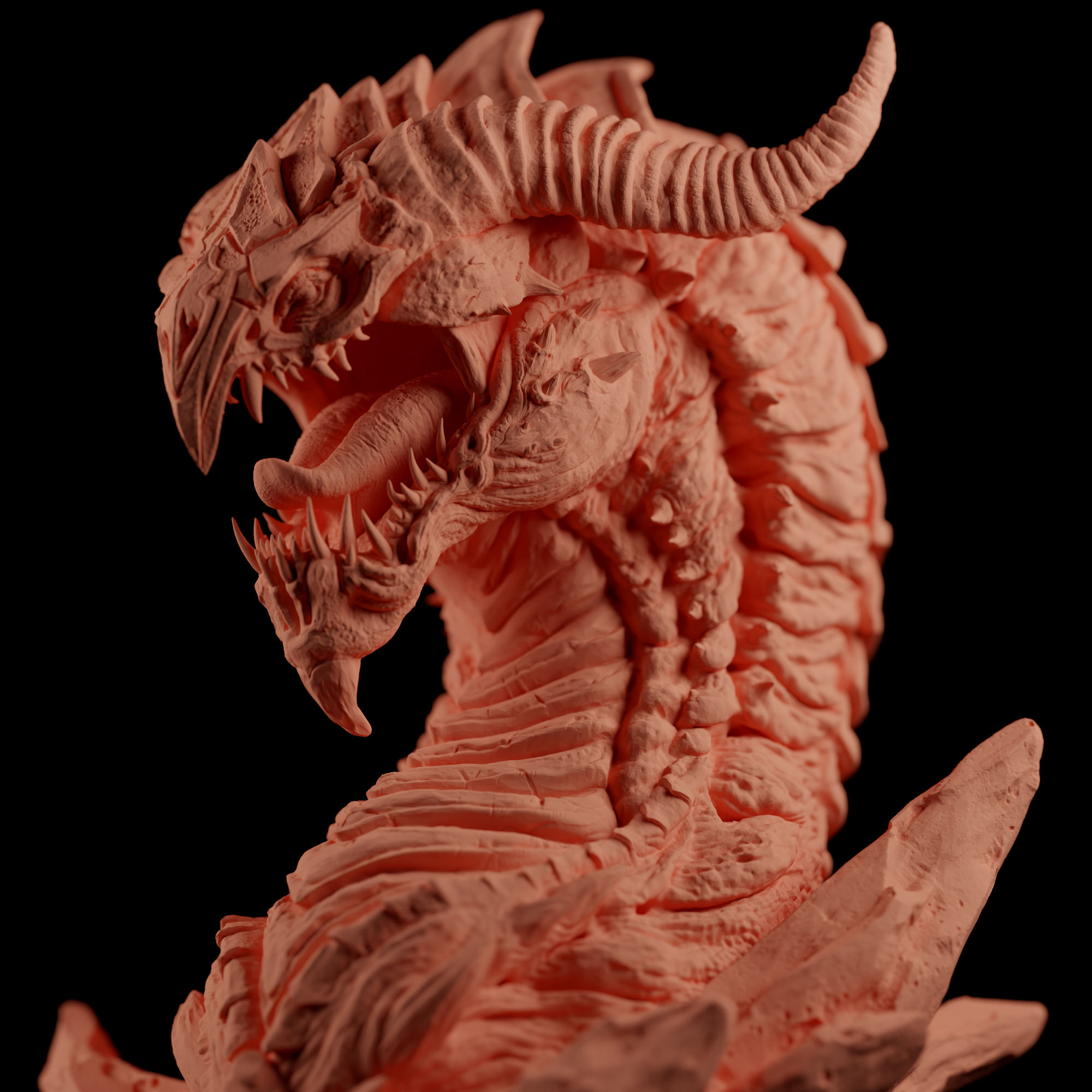
Diffuse
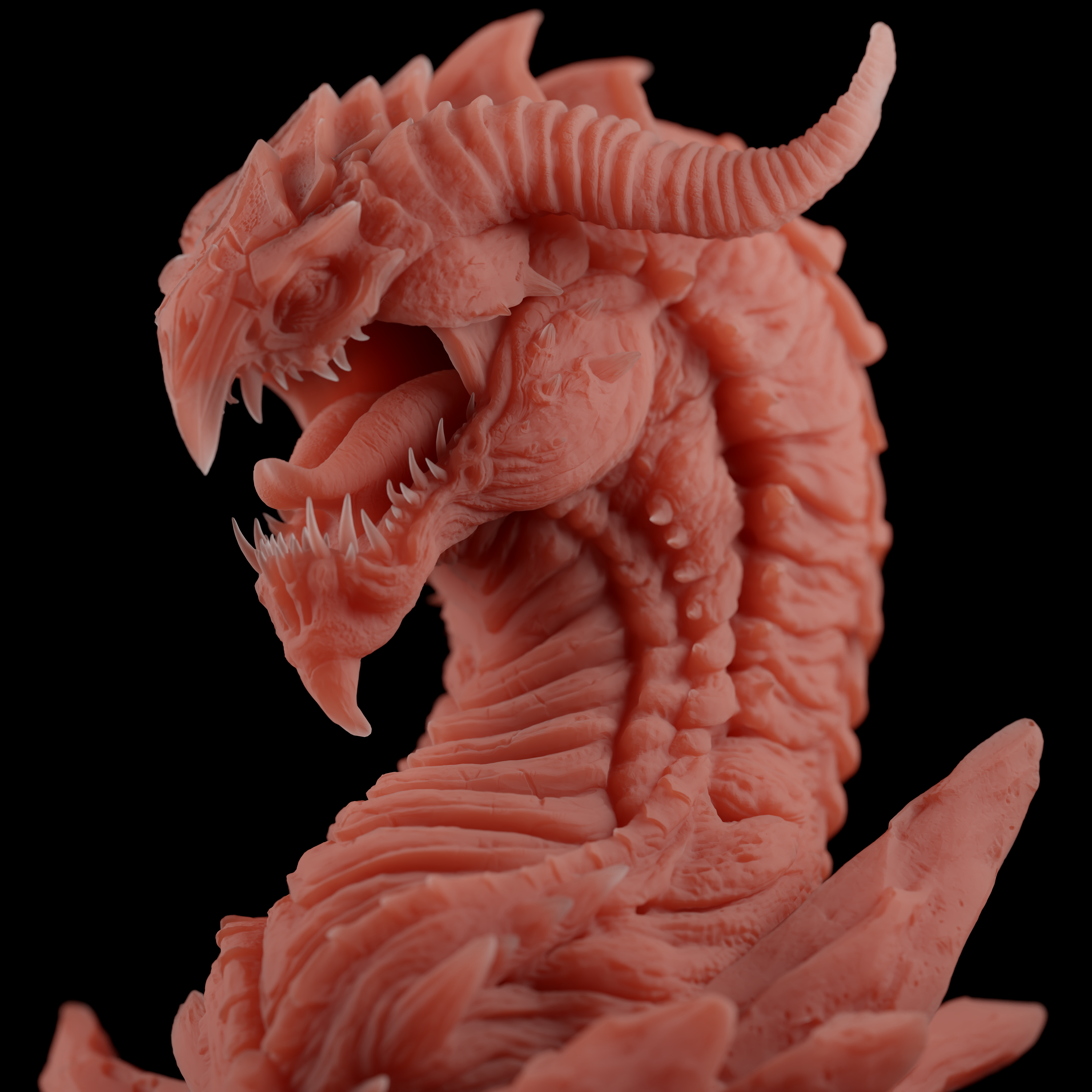
Subsurface scattering
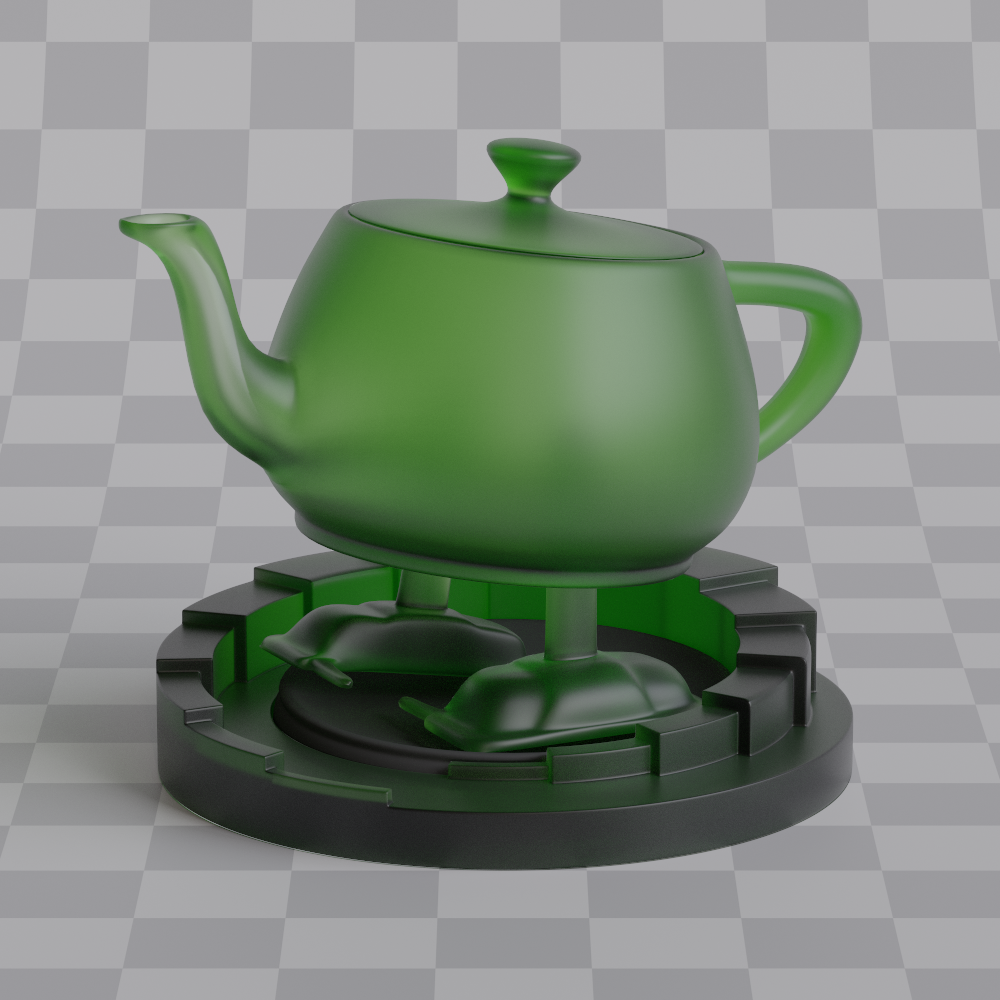
Among other effects that are possible to simulate, is volumetric glass. It's basically a glass object filled volume of anisotropy 1.0, so the ray will travel in a straight line. This way, instead of tinting the color on refraction, the color is tinted as ray travels through the object. So the color is less saturated in thin areas and more saturated in thick ones. It's just an opinion, but I think it looks way better than normal glass.
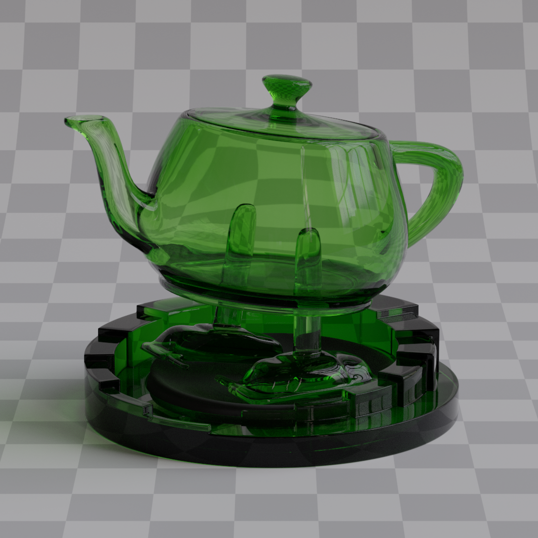
IOR = 1.25
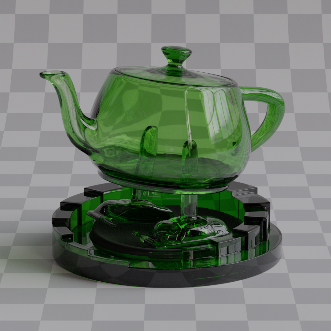
IOR = 1.50
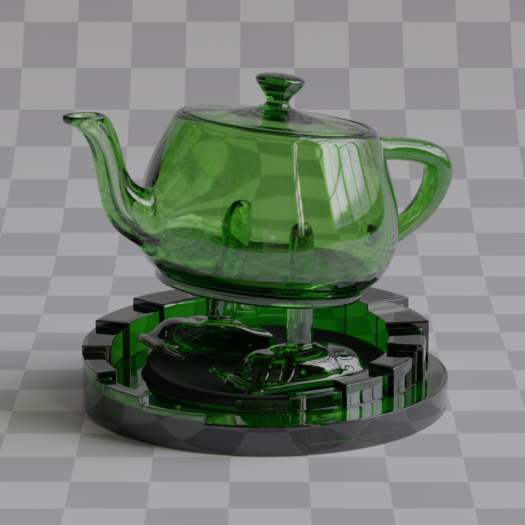
IOR = 1.75
IOR = 1.50
Roughness = 0.0
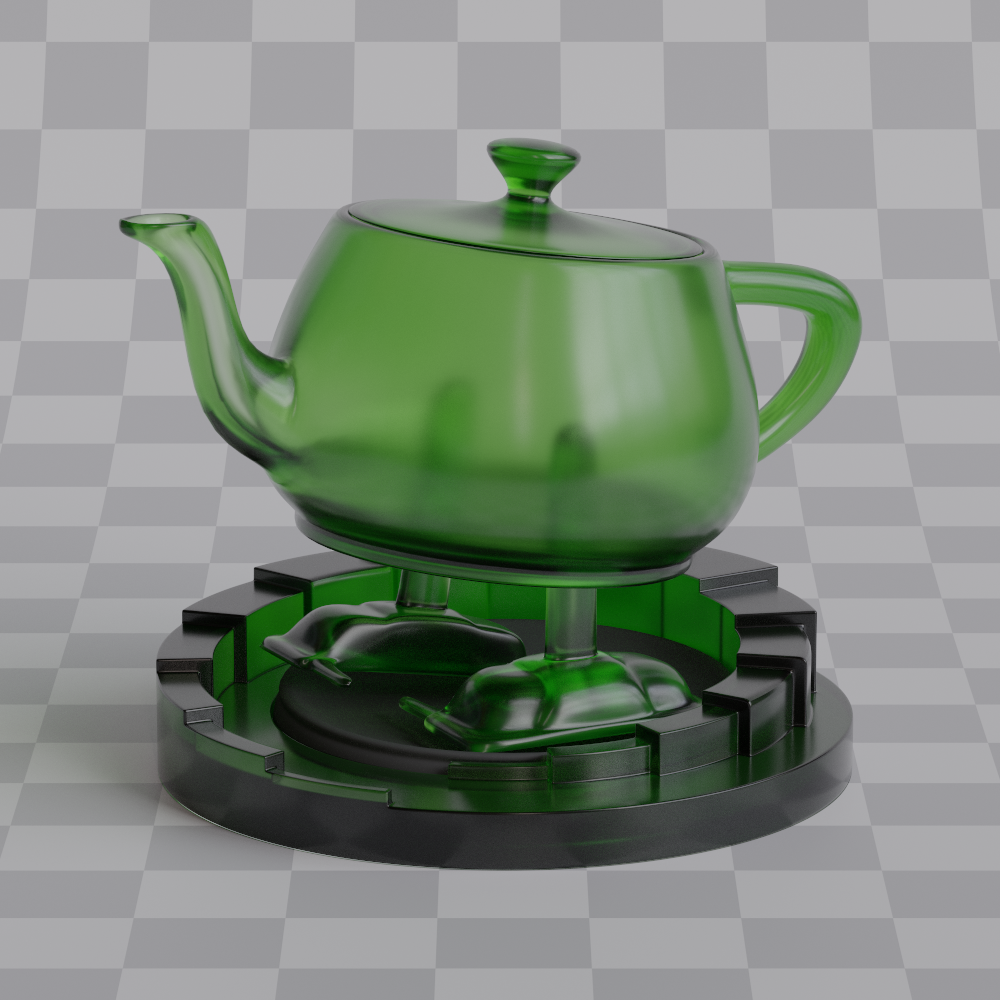
IOR = 1.50
Roughness = 0.2
IOR = 1.50
Roughness = 0.4
When it comes to AABB volumes there's really not much to see without any explicit light sampling. The most you can do, is place fog around the scene and wait eternity for it to converge. Probability of a light ray bouncing in a volume multiple times and then hitting a light source is abysmally low, most of the paths won't contribute anything. Image below is an example of that, it took 1 millions samples per pixel (2'073'600'000'000 samples in total, god bless GPUs) to look somewhat decent, I had to path trace this for almost 2 hours, which is quite long considering how simple the scene is.